Friday, February 28, 2014

Final Year Project 2(Hardware) Week3

Title: Design PCB layout to perform circuit connection

Objectives:

  • To get familiar with the software to design a PCB layout 
Procedure:

  • Install the software to design a PCB layout


Software to Design Circuit

Software to design PCB
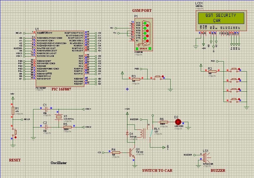
  • Copy the circuit from the Proteus simulation that are designed before this and draw again at Livewire software.
Result and Analysis:
  • The LiveWire software and PCB Wizard are working together, the LiveWire software are especially to design a circuit connection. While the PCB Wizard are imported the file from LiveWire software to perform the PCB layout designed. (Important step:Remember it must working together)
  • Draw back the circuit that has been design and simulate by using Proteus simulation. This step are needed to do it carefully because any error connection will be effected at the PCB layout designed.
Draw circuit at LiveWire software
  • Convert the design circuit to the PCB layout that will be performed by the PCB wizard software

PCB layout after converted from design circuit
  • The picture above only display the PCB design for PIC16f877a circuit only, the full design PCB for the circuit are shown below. Actually I have separated my circuit to 3 part: 
  1. PIC16F877A circuit
  2. MAX 232 circuit
  3. Alarm circuit
  • The all circuit that I have converted to PCB design are shown as below

Full design PCB circuit
Conclusion:

  • This session are succesfully done because I have learned how to design a PCB circuit design by using the selected software LiveWire and PCB Wizard. The PCB design need to be designed properly and double checked the connection to make sure that is doesn't have the short circuit situation. 

Wednesday, February 19, 2014

Final Year Project 2(Hardware) Week2

Title: Testing the coding with the GSM module

Objective:


  • To testing and interface the real GSM module with the simulation circuit by Proteus
  • To test the RS 232 cable weather it can works with the computer
Procedure:


  • List all the item that need to be tested during this session
  1. GSM modem by Wavecom
  2. RS 232 cable & conncetion cable
    RS 232 cable

    Connection cable between GSM & RS 232 cable
Result and Analysis:
GSM module connected to the computer

  • The cable RS 232 and GSM module are tested during this session and connected through the usb port at computer
  • GSM module give a positive feedback, which means it successfully connected and tested by using Proteus simulation. It also can send and receive the message from cellphone to the GSM module.
Conclusion:

  • As a conclusion, this testing session are successfully done. The GSM module are give a positive feedback to the simulation circuit that can connected and interface with each other. This session are to make sure that the actual GSM module that can connected with the simulation circuit. So, I can proceed to next step, design the PCB layout for the real hardware circuit. 


Tuesday, February 11, 2014

Final Year Project 2(Hardware) Week1

Title: Software testing and assemble coding using Microcontroller PIC16F877A

Objective:

  • To design a circuit to perform GSM system + Microcontroller
  • To testing weather the coding are suitable and well performed
Procedure:
  • Using Proteus v7.8.2 software to design circuit and MPlab + Hitech Compiler to implement the coding part

Protues Simulation v7.8.2

MPlab compiler by Microchip

Hi-Tech compiler to perform C language
Result and Analysis:
  • Circuirt are been tested and the modification part are upcoming updated.
Simulation by Proteus Software

Header Coding to perform circuit
Conclusion:
  • As a conclusion, the circuit and coding are implemented and function well. The C coding and tested circuit are react with each other.