Thursday, November 28, 2013

Budget

Week 12

Estimated cost to build this project


Table 3: Approximation budget to build prototype product

The total approximation budget are about RM400 to build a prototype project, and the price are more cheap than the others advance alarm car product.

a    If the actual security plus system are applied to the car, the cost are amount RM700 to RM800.

Thursday, November 21, 2013

Work Plan

Week 11

The planning of this project is made to estimate the time of its completion. The planning is divided into 2 semesters. At the semester 1, the entire requirement needed is complete according to the Table 1 below.
Table 1: Work Plan for FYP1

At the semester 2, here is the planning to complete this project. This entire task needs to complete at the time shown in the Table 2. To make a schematic design, 4 week is needed to complete the entire layout. The massive thing during next semester is to write a coding. It’s needed around 5 week to complete the programming. This entire task needs to complete before week 13 next semesters according to my target shown in the Table 2.

Table 2: Work Plan for FYP2


Tuesday, November 12, 2013

Benefit of Project

Week10

Benefit


Applications and Advantages

There are a lot of benefits to security that most people often overlook. Having a car alarm/vehicle security system isn’t just about protecting vehicle from potential thefts. It’s also about convenience and functionality.

Applications

1. Stolen vehicle recovery.
2. It is used for food delivery, car rental companies and      also government field.

Advantages

1. It provides more security than other system.
2. From the remote place we can access the system.
3. By this we can position the vehicle in exact place.
4. Doesn’t need human to monitor the system
5. Only the owner can switch on the power to make the car moves back.
6. Use the battery car to operate the system.
7. This system is more cheaper and efficient than the actual advance alarm car.

Disadvantages
1.The main problem is when the GSM system didn’t receive any line, it couldn’t work properly.
2.If one of the circuits did not connected well, the circuit will not function too. 

Thursday, October 31, 2013

Wiring system Operation

Week8


Figure 6: The connection GSM and Microcontroller to Car Wiring


Figure 6 above are shown the example of connection from GSM to Microcontroller. The GSM that are used in this example are Siemens TC35 from Cytron Technology. Its operate from 7 to 12 Vdc. To connect to the Microcontroller, usually the output voltage from GSM is around 3V, but the input from Microcontroller must 5v. It must be step up by using Logic converter 4 channel (LC04) that converted from 3v to 5v output to connected to SK40C(PIC16F877A). The output from Microcontroller will be connected to a relay and connected to the ignition switch system. The relay is connected to the car wiring as shown in the Figure6 above.

For the connection GSM to Microcontroller, please refer to Cytron Technology Tutorial: 

Connection from ignition switch to relay, please refer to:

Thursday, October 24, 2013

Methodology

Week7


Diagram explanation


Figure 4

The circuit that I design are based on the Microcontroller subject that I have learned in Unikl BMI. Microcontroller unit in this diagram are using the PIC16F877A which means it has the 40pin IC and 4 port. The Microcontroller are as the main circuit that control the GSM module circuit and power unit of the car as Figure 4 shown above: http://tjournal.org/tjst_november_2012/4.pdf
First, the power supply are taken from the main power of the car. The output for current are connected to the microcontroller system to turn on the microcontroller PIC16F877A. The GSM module are powered by using the car system and it connected at the input of microcontroller. Sensor are using in this circuit, the 2 sensor that are used are at the doors and boot of the car that are connected to the input for microcontroller.  For the output for the microcontroller, it connected to the main switch (key switch) for the car and alarm system. The key switch is functioning to turn off when it gets the signal form GSM system and react to the microcontroller and will demobilize the overall car system. In the other word, it will shut down the overall wiring system that is used to operate the car. 


The operation system

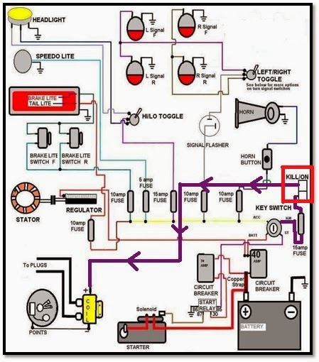
Figure 5: Overall Ignition System Car

First, the power supply from car battery is connected to the microcontroller and GSM module that is in the red colour box as represent the relay.. When the car are stolen, the owner will sent the text message to the GSM module. Then, the GSM will react and give data to the Microcontroller. Microcontroller will trigger the switch that connected to the sensor and alarm system. The alarm will start to turn ‘ON’. While the alarm on, the microcontroller also trigger the switch that connected to key switch that are functioning to demobilize the overall current to the ignition system as shown in Figure 5 above : http://www.ripper1.com/tech/wiring.php

After demobilize, the Microcontroller needs to wait another text message from the car owner to immobilize the car back. After receiving the text message, the car will operate normally and the thief is being captured.


Wednesday, October 16, 2013

Literature Review

Week6


Before this, peoples are using the manufacturer security alarm only. The thief had an experience regarding this security alarm, which means they work is getting easier to steal the car because they had well known about the alarm circuit. They know when the time to cut-off the alarm and had well known about the system. So, it is important to double protect the security of the car.
 Antitheft security system utilizes an embedded system design with Dual Tone Multi Frequency (DTMF) and a GSM to monitor and safeguard a car. It secures the car against theft. Upon activation, it automatically demobilizes the car by disconnecting the ignition key supply from the car battery. This now makes it impossible for anybody so starts the car, let alone moving with it. In an attempt of theft through the car doors or boot, the system sends text message to the car owner and at the same time starts up an alarm. This design popped out due to the increasing rate at which packed cars are stolen especially in our country, but with this design this packed car is being monitored irrespective of where it is packed, provided there is GSM network coverage. From the research conducted, it was found out that majority of the existing car security system uses only alarm, and doesn’t send text message to the car owner let alone of demobilizing the car. But with the use of GSM network, the owner is guaranteed that the car will send text message to his phone, and at the same time, have people around alerted of what is happening. Added to this is that the car will not be move because it has been demobilized. To make sure that the circuit are possibly run are by using the PIC16F877A microcontroller.

The main circuit are controlling the overall circuit either the GSM circuit or the supply current to overall car system.  The Microcontroller PIC16F877A is chosen because of this controller I have learned in Microcontroller subject in Unikl BMI. It can work on different language either the assembly language or the C language. But mostly student will prefer C language because it would be easier to understand and can run simply that the assembly language. The program needs to compile as the HEX file to apply to the circuit.

Figure below are shown the example product that are already in the market, this product are quite similar with my project but the price are quite expensive compare to my project:

Item1

GEO TRACKER Micro GSM GPS Google Map Tracker


Price: RM 988
Function: GPS,GSM, Anti-theft function(Demobilize)
Made in: Taiwan


Item2

IES GSM/SMS Vehicle Security System

Price:RM 2,388.00
Function: GPS,GSM, Anti-theft function(Demobilize),Various Alarm type
Made in: U.K