Friday, March 14, 2014

Final Year Project 2(Hardware) Week5


Title: Readjustment the PCB layout

Objectives:

  • To make sure that the PCB layout design are suitable with the virtual circuit
  • To compromise with the supervisor about the PCB layout design 
  • But the component part to build a virtual circuit
Procedure:


  • Open the  PCB Wizard software that contain the previous PCB design and rebuild it to make it more compatible and alternate with the virtual circuit. 

Previous PCB design

  • From Proteus software, list down all the electronic component that needs to buy at Jalan Pasar
Result and Analysis:

  • New PCB design for Microcontroller circuit are form


PCB Wizard: Normal view
PCB Wizard: Real World
The previous PCB design for MicroController circuit are contain little error that have the problem regarding the supplied from VDD and VSS at pinout Microcontroller 11,12,31 and 32 needs to be redesign and the result are shown as the Figure above. The view for real world PCB design are shown as above figure, which means all the component to build the virtual are stated as figure above.


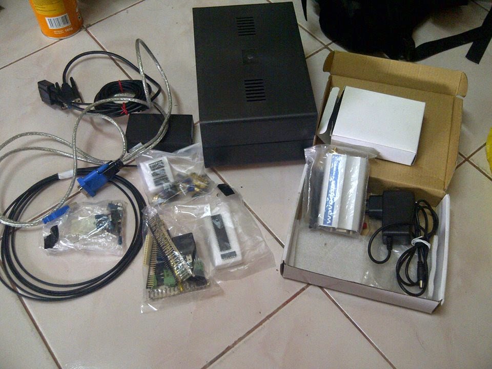
  • All regarding electronic component that have been bought from jalan pasar


 Conclusion:

As a conclusion, the PCB design are confirmed by supervisor and the actual PCB circuit must be created after this. All the actual component such as Microcontroller,resistor,switch,boxes,capacitor,PCB board,LCD 16x2 and etc are bought from Jalan Pasar. All the component are completed, the circuit can be tested by the using breadboard first after this. 

Thursday, March 6, 2014

Final Year Project 2(Hardware) Week4

Title: Connecting Relay 5vdc with Microcontroller Circuit

Objectives:

  • To testing the relay 5vdc with the 12vdc from car battery
  • To check either the output frrom Microcontroller can connected to relay and transistor
  • To test the function of IC ULN2003A that can replace the output from Microcontroller 5vdc to 12vdc
Procedure:

  • Edited the relay part that combined with the transistor TIP 122 and replacing with the ULN2003A
Relay diagram that used TIP 122
  • The ULN 2003A testing connection output
ULN2003A output
  • The ULN2003A replacing with the TIP122
ULN 2003A connect with relay connection
Result and Analysis:

  • The transistor TIP122 are control as a switching to active the relay coil, which means the output controller are connected at TIP 122 and the function are react as a ground to activated the relay coil. But the main problem is the transistor isn't give any feedback because the relay are not turn 'on 'after given output from Microcontroller 5v. 
  • The specification to turn 'on' the relay are 5vdc but the MicroController output are only gieven 2.7vdc, so the relay cannot function well. 
  • To solved this problem needs to find some devices that can step up/stiwch the voltage to 12vdc. because the 5vdc relay can support until 12vdc.
Relay 12vdc turn on
Conclusion
  • The output fro Microcontroller are problem, it supposed to give 5vdc but the actual value when practical session are given the right feedback. So, the output must be step up to 12vdc. Due tho the simulation, the output are succesfully step up by using ULN 2003A. But, dont know about the practical is it valid or not. 

Friday, February 28, 2014

Final Year Project 2(Hardware) Week3

Title: Design PCB layout to perform circuit connection

Objectives:

  • To get familiar with the software to design a PCB layout 
Procedure:

  • Install the software to design a PCB layout


Software to Design Circuit

Software to design PCB
  • Copy the circuit from the Proteus simulation that are designed before this and draw again at Livewire software.
Result and Analysis:
  • The LiveWire software and PCB Wizard are working together, the LiveWire software are especially to design a circuit connection. While the PCB Wizard are imported the file from LiveWire software to perform the PCB layout designed. (Important step:Remember it must working together)
  • Draw back the circuit that has been design and simulate by using Proteus simulation. This step are needed to do it carefully because any error connection will be effected at the PCB layout designed.
Draw circuit at LiveWire software
  • Convert the design circuit to the PCB layout that will be performed by the PCB wizard software

PCB layout after converted from design circuit
  • The picture above only display the PCB design for PIC16f877a circuit only, the full design PCB for the circuit are shown below. Actually I have separated my circuit to 3 part: 
  1. PIC16F877A circuit
  2. MAX 232 circuit
  3. Alarm circuit
  • The all circuit that I have converted to PCB design are shown as below

Full design PCB circuit
Conclusion:

  • This session are succesfully done because I have learned how to design a PCB circuit design by using the selected software LiveWire and PCB Wizard. The PCB design need to be designed properly and double checked the connection to make sure that is doesn't have the short circuit situation. 

Wednesday, February 19, 2014

Final Year Project 2(Hardware) Week2

Title: Testing the coding with the GSM module

Objective:


  • To testing and interface the real GSM module with the simulation circuit by Proteus
  • To test the RS 232 cable weather it can works with the computer
Procedure:


  • List all the item that need to be tested during this session
  1. GSM modem by Wavecom
  2. RS 232 cable & conncetion cable
    RS 232 cable

    Connection cable between GSM & RS 232 cable
Result and Analysis:
GSM module connected to the computer

  • The cable RS 232 and GSM module are tested during this session and connected through the usb port at computer
  • GSM module give a positive feedback, which means it successfully connected and tested by using Proteus simulation. It also can send and receive the message from cellphone to the GSM module.
Conclusion:

  • As a conclusion, this testing session are successfully done. The GSM module are give a positive feedback to the simulation circuit that can connected and interface with each other. This session are to make sure that the actual GSM module that can connected with the simulation circuit. So, I can proceed to next step, design the PCB layout for the real hardware circuit. 


Tuesday, February 11, 2014

Final Year Project 2(Hardware) Week1

Title: Software testing and assemble coding using Microcontroller PIC16F877A

Objective:

  • To design a circuit to perform GSM system + Microcontroller
  • To testing weather the coding are suitable and well performed
Procedure:
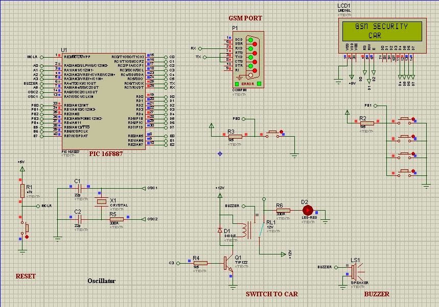
  • Using Proteus v7.8.2 software to design circuit and MPlab + Hitech Compiler to implement the coding part

Protues Simulation v7.8.2

MPlab compiler by Microchip

Hi-Tech compiler to perform C language
Result and Analysis:
  • Circuirt are been tested and the modification part are upcoming updated.
Simulation by Proteus Software

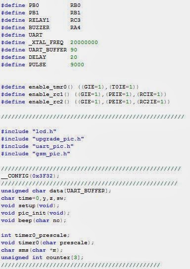
Header Coding to perform circuit
Conclusion:
  • As a conclusion, the circuit and coding are implemented and function well. The C coding and tested circuit are react with each other. 


Thursday, December 12, 2013

Using relay to kill the power off

Week14

Example 1)


Youtube Link: http://www.youtube.com/watch?v=xi5DPg_iEYs


Example 2)


In this video,there is an example to Kill The Ignition System as the video did. So,I just upgrading the system by adding the GSM + MicroController and combining together with the relay system. Hope participant will enjoy and keep following my blog ;)

Wednesday, December 4, 2013

Conclusion

Week 13

As a conclusion, this Project for Development of GSM Based Vehicle Anti-theft Security System is successful though. The projects are combined with the greatest combination ever that is combining the microcontroller with GSM. This project is actually will make a new evolution for security car system. For these reason, it is important to develop methods to show a different ways of marketing to popularize their products.

This idea can be apply in the field of government and other use. It will show that electronic field has a lot of criteria to impose in engineering section. Finally, the future improvement will most likely consist of interactivity security system. The proper security system is implementing to get a better protection and utilize the protection system against theft. Hopefully that this project can compete with the other product at the market.